How to completely configure your Mikrotik router - part 1
Author: Gergő Fándly
Date: 2024-09-04
Whether you’re managing the network infrastructure for a small business, a large corporation, or simply your own home, a MikroTik router is a great choice. Their routers are very capable and offer a great price-to-performance ratio.
Even their most basic 25$ router comes with a full RouterOS (MikroTik’s router operating system) license and allows you to modify every aspect of your configuration. On the downside, you can modify every aspect of your configuration, which can be overwhelming, especially if you’re only familiar with the simple interface of most home or small business routers.
In this series, I’m going to walk you through every step of the configuration process, including setting up your WAN connection, configuring IPv6, setting up VLANs, setting up VPN access, and configuring a secure firewall. This guide requires no preliminary knowledge, but some basic understanding of networking is beneficial.
In this part, we’re going to do the basic configuration, set up a simple network, and configure the firewall.
Choosing a router
For the first step, you need to get a MikroTik router. I’d recommend getting a device that is just your router and get a separate access point.
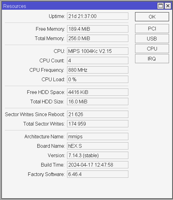
Even though their cheapest router offerings start at around 25$ MSRP, I’d recommend getting something more performant. If you’re looking for an inexpensive router that will never let you down and will allow you to fully utilize a 500 Mbps uplink connection, I’d recommend going with the hEX S, or if you want a router + AP combo, you can go with the hAP ac3.
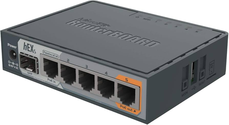
These will both suit well a home or a small business setup (up to around 20 users). If you need something more performant, you can browse through MikroTik’s hardware offerings here.
Getting started
Once you’ve got your router and connected all the necessary wires (power, WAN internet line, and other devices) you will need to configure it.
RouterOS offers a lot of different interfaces you can use for configuration, but the two simplest are WebFig (a browser interface) and WinBox (an application you have to install on your device). I’m recommending to use WinBox. It’s for Windows only, but you can also run it under Linux and MacOS using Wine without any additional configuration.
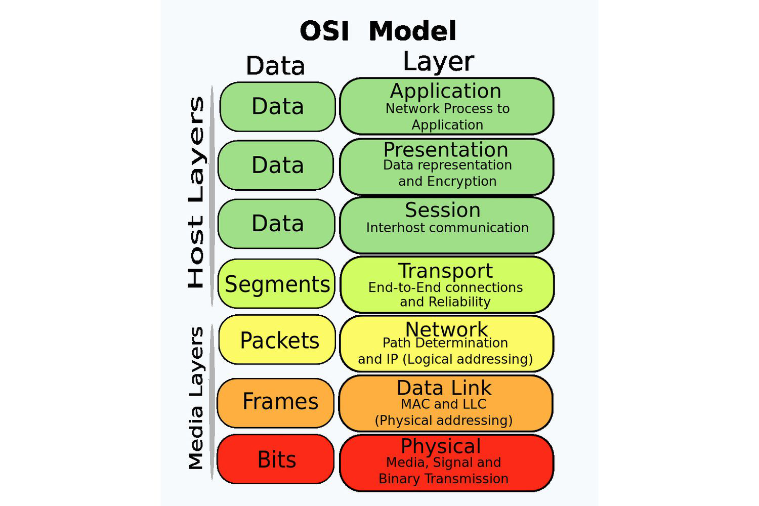
WinBox also has a special feature: it can work on L2 of the OSI model. What this means is that even if you mess up your network configuration and your device or your router no longer gets an IP address, you can still connect to it using the MAC address of the router. During the first-time setup, this is equally helpful since you don’t need to figure out what port you need to connect your device to and what IP address it is going to get. You just plug an RJ45 cable into any of the router’s ports and connect to it using its MAC address.
So to get started with configuring, download WinBox from here, start it up (if you’re on Linux or Mac start it using wine winbox.exe) and it will auto-discover your router on the neighbors tab. If it does not, just punch in the MAC address of the router (found on the back of the device) to the Connect to field and set the username to admin. The password is empty by default on most of the devices, but some might have a default password set which can be found on the back of the device as well.
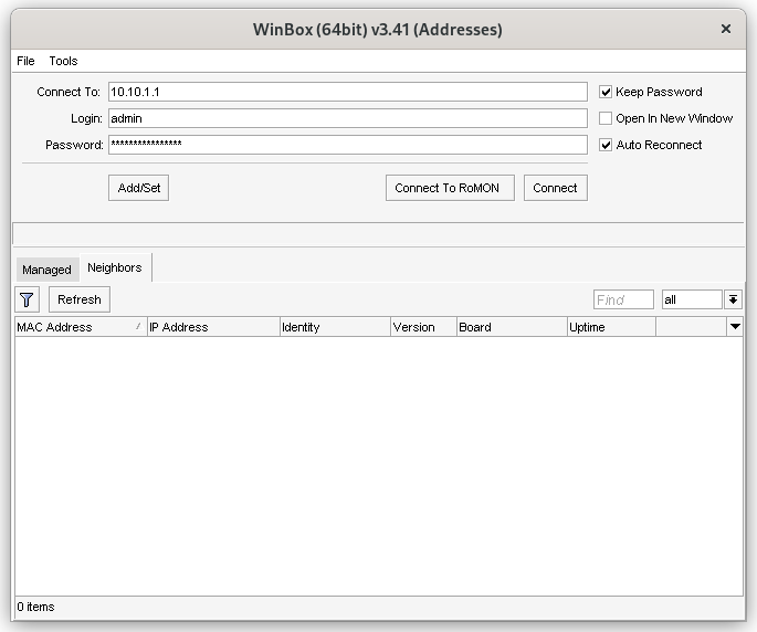
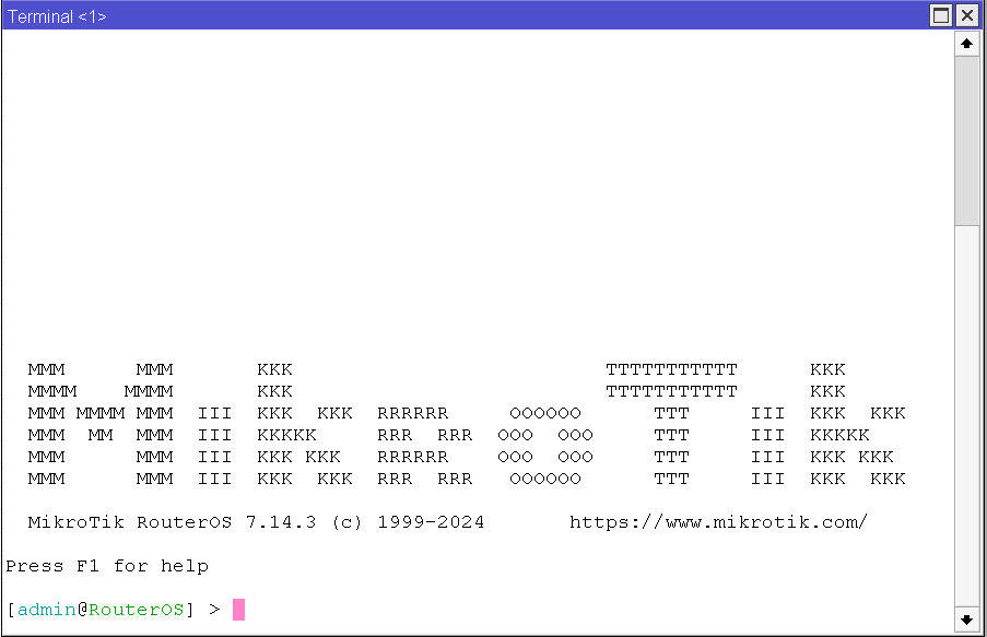
Hit connect and you will be greeted with the following screen:
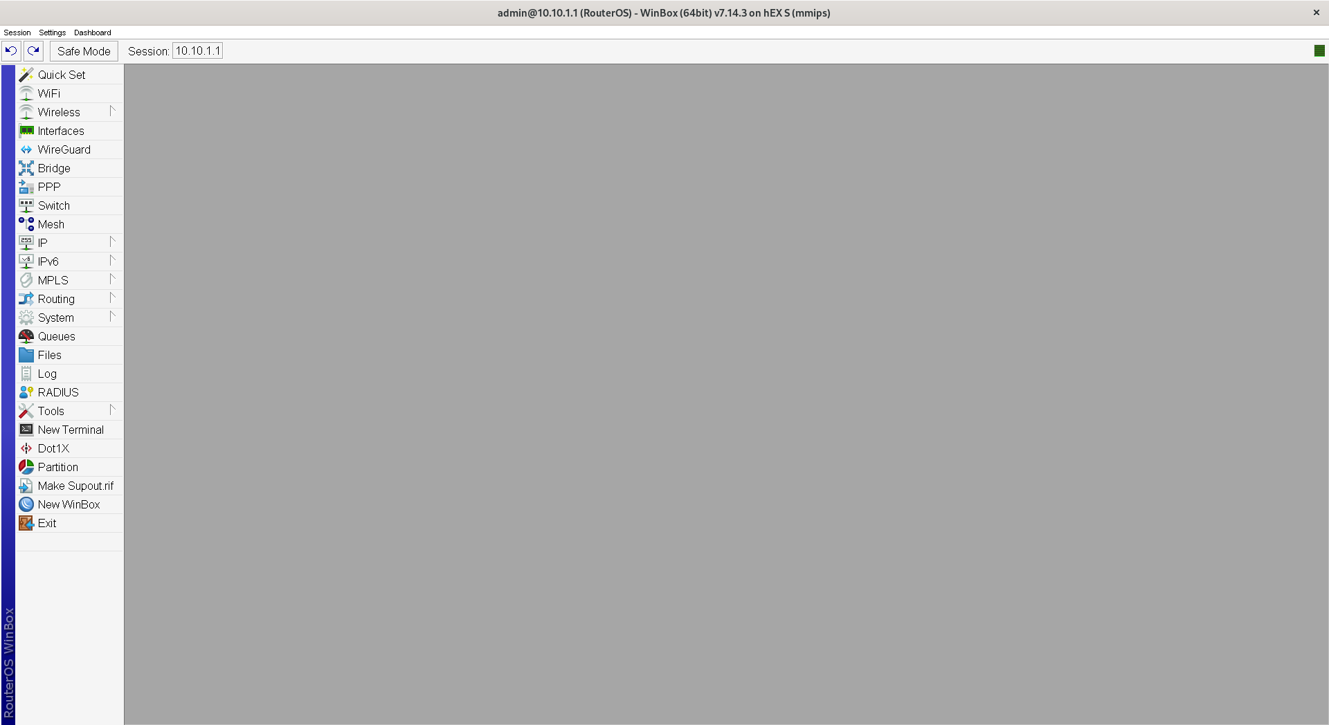
The first thing you need to do is to reset your configuration. This way we can assure that we’re starting from a clean state with no default settings. Go to System -> Reset Configuration and check No Default Configuration and Do Not Backup, then click the Reset Configuration button.
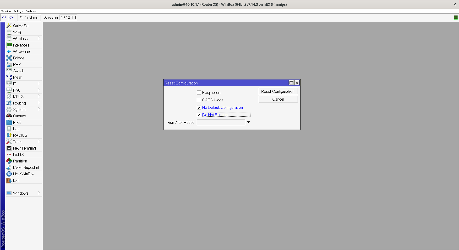
After this, we might need to reconnect to the router.
As the very first step, change the administrator password. Go to System -> Password and change it to something secure.
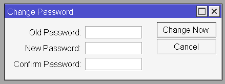
Now we’re ready to do the actual configuration.
Configure the network interfaces
First of all, we need to configure our interfaces. Click on the Interfaces button which will bring up a new window with our default interface list. In the case of the Hex S it will contain interfaces named ether1 through ether5 representing the 5 RJ45 ports on the device and sfp1 representing the SFP cage. It also contains a lo interface which is the loopback interface. The R in the first column represents that the interface is Running (i.e. you have something connected to it). You can rename any of the interfaces, but I’d recommend leaving them as-is since it’s easier to identify them this way. If you need to add some custom information (like that into ether2 you have an access point plugged in, use the comment feature – Right click -> Comment).
By default, all of the ports act like a separate network interface, which might be desirable for you. But let’s assume you are going to use your MikroTik router as a “normal” router which has 1 WAN port and 4 LAN ports. To achieve this click on the Bridge button from the sidebar which will bring up a new list. We’re going to create a bridge that will make use of the router’s built-in switch chip to make ports 2-5 act like they are a switch not a separate interface, while leaving port 1 for the WAN connection.
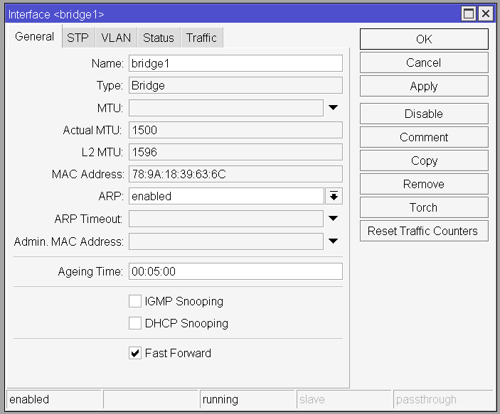
Click on the Plus button from the Bridge screen and make sure Fast Forward is checked. Leave everything else as-is and click OK. This will create a new interface named bridge1.
Now we have to assign which ports we want to participate in this bridge. Go to the Ports tab of the Bridge window and click the Plus button. You need to select which interface you want to participate in which bridge. Select ether2 and bridge1 and leave the rest of the settings as default.
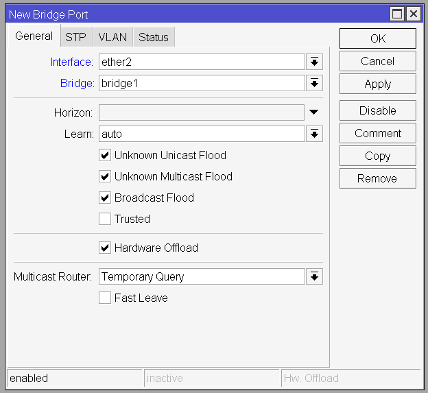
Now repeat this for ether3, ether4 and ether5. The final screen should look something like this:
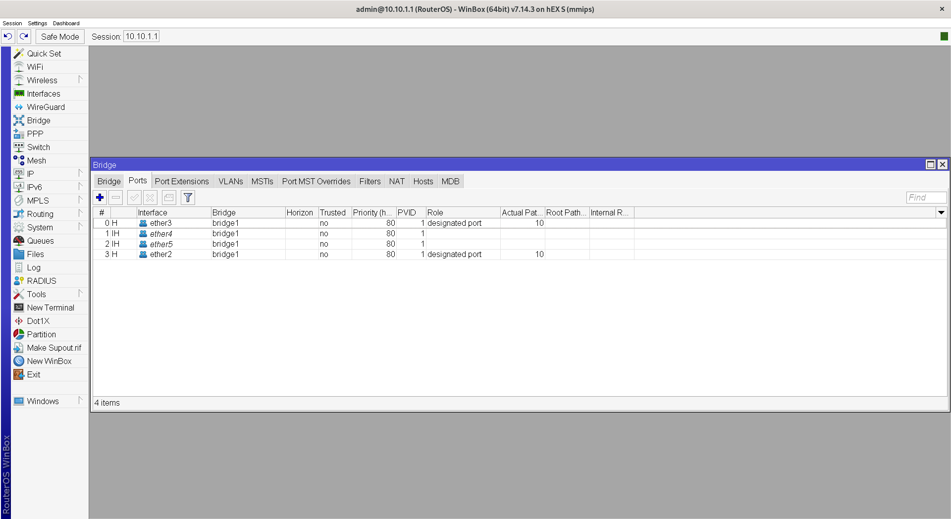
Now if you go back to the Interfaces window you will see that a new interface (bridge1) appeared and that an S letter appeared in front of interfaces ether2 - ether5. The S stands for Slave, meaning that this port is managed by another interface.
Now we’re going to create some interface lists to make our life easier. Interface lists are just what they sound like – a list containing some interfaces. This will help us later on when we will be able to just reference an interface list and won’t be required to reference each interface manually (like in the firewall rules).
Initially, the router has 4 default interface lists:
- all: contains all the interfaces
- dynamic: contains all the dynamic interfaces
- static: contains all the static interfaces
- none: contains no interfaces
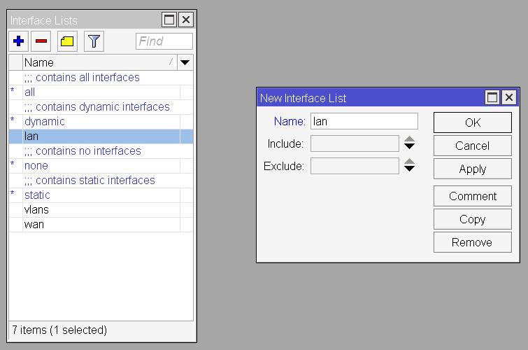
Now we’re going to create 2 more: lan (containing all of our LAN interfaces) and wan (containing all of our WAN interfaces).
To do this, go to the Interface List tab of the Interfaces window, click on the Lists button then click the Plus button. Enter the name lan and click OK. Repeat this for wan as well.
And now we have to do the same thing as when creating the bridge – we have to assign the interfaces to the lists. We’re adding the interface bridge1 (remember that this interface controls interfaces ether2, ether3, ether4, and ether5) to the lan list, and to the wan list we’re not adding anything yet since we do not have a WAN interface yet.
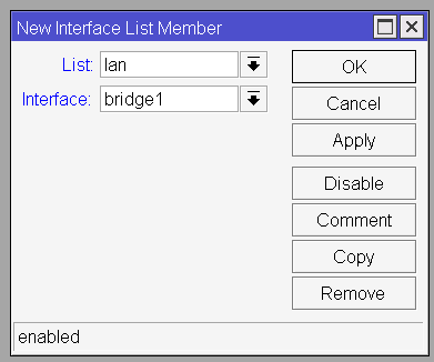
You might ask: why bother with creating these lists when we’re only adding a single item to them? Spoilers ahead: we will add more interfaces to them later on, but even if don’t, we might do so in the future, and this helps us future-proof our configuration.
Configuring the WAN connection
Now that we have our interfaces set up, it’s time to configure our WAN connection. I’m going to assume your ISP uses PPPoE (you have a username and a password you have to use to connect to the internet).
To set up your PPPoE connection we have to create a new interface for it. Open the Interfaces window and click on the Plus button. From that list select the PPPoE Client option.
On the General tab make sure that under the Interfaces option ether1 is selected. This means that our PPPoE client will use the ether1 physical interface to initialize the connection.
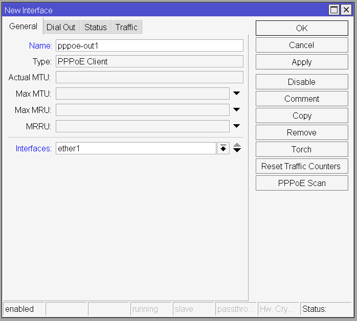
Now switch to the Dial Out tab and enter the username and the password you got from your ISP. You might have to contact them to get these or you can extract this information from your old router. Leave the rest of the settings on the default value.
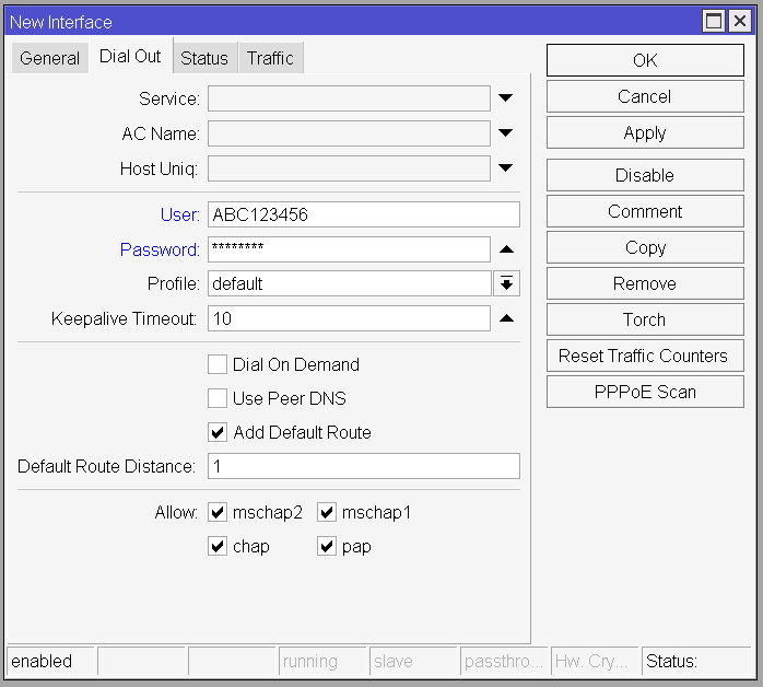
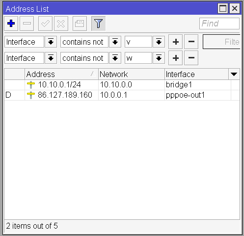
Click OK and it should automatically connect. To verify that it’s working as expected double click on the newly created pppoe-out1 interface and check the bottom right corner. It should say Status: connected. You can also verify if your router successfully got an IP address. On the side panel click IP -> Addresses and there should be a record with a D (for Dynamic) on the first column for the interface pppoe-out1. This is the IP address your router got from your ISP.
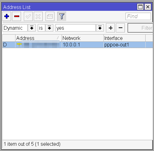
This does not mean that your devices can connect to the internet from now on. Even though your router can access the internet now, your devices don’t even get an IP address. We’re going to fix this in our next step.
As a final step go back to the network interfaces list and add the pppoe-out1 interface to the wan list.
Configuring the LAN network
Now it’s time for your devices to get those IP addresses and finally get some internet access.
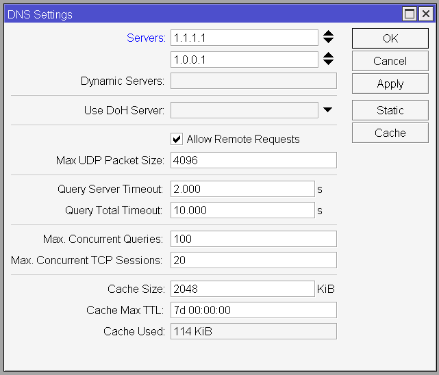
To do this we will configure our DNS client first. It’s not strictly necessary, but it’s recommended to do so. On the sidebar click on IP -> DNS and add your preferred DNS servers. You can add as many as you want using the arrows right to the Servers field. I’d recommend going with 1.1.1.1 and 1.0.0.1. These are Cloudflare’s DNS servers which are blazing fast and (presumably) respect your privacy by not selling your data.
You also need to check Allow Remote Requests to allow devices on your LAN network to use your router as their DNS server.
Quick tip:
If you ever need to set some custom DNS records you can click on the Static button and set them, and you can also check the cached records and flush the DNS cache by clicking on the Cache button.
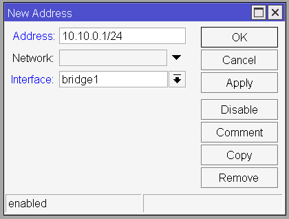
With the DNS settings out of the way, we can configure the internal IP address of the router. To do so, pull up the IP -> Addresses window. This is the time to decide what our network block is going to be. I’ll be going with 10.10.0.0/24, but you can use any IP address block reserved for private networks. You can refer to this list.
To add this address click on the Plus button and enter 10.10.0.1/24 to the Address field and for the Interface field select bridge1. You can leave the Network field empty since it will get automatically populated based on the address and the subnet mask (/24) we defined.
If you were to manually assign a static IP address to the devices on your network you could already ping the router. But assigning static IP addresses is not a pleasant experience, so we’re going to configure a DHCP server.
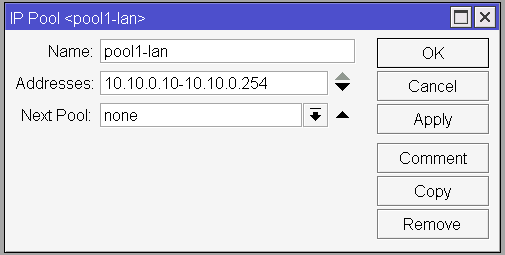
To configure the DHCP server first we need to create an address pool from which the router will assign the IP addresses. Open up the IP -> Pool window and click on the Plus icon. Name it like pool1-lan and in the Addresses field enter 10.10.0.10-10.10.0.254. This means that the DHCP server will assign IP addresses from this range. I’m leaving the 10.10.0.1-10.10.0.9 range out of the pool since 10.10.0.1 is already taken (it’s our router’s IP) and this leaves us 8 more IP addresses we can statically assign should we need to do so (for example for a media server, for access points, etc).
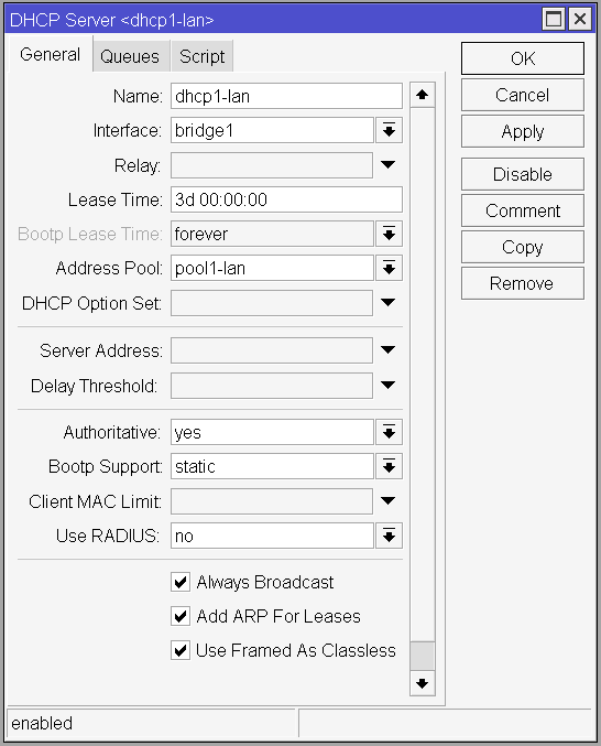
Now we have to create the DHCP server itself. Go to IP -> DHCP Server and click the Plus button. Name it dhcp1-lan and for the interface select bridge1. You can set the lease time to whatever you want, but I’m recommending 3 days. This means that if a device reconnects to the network in 3 days, it will get the very same IP address as the first time. To achieve this enter 3d 00:00:00 as the Lease Time. For the Address Pool select pool1-lan and check the Always Broadcas and Add ARP For Leases checkboxes. The final result should look like this:
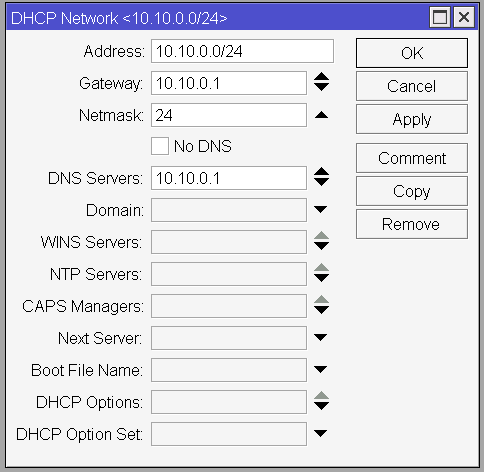
Now that we have a DHCP server, we need to create a network configuration for our LAN network. Go to the Networks tab of the DHCP Server window and click the Plus button. You need to enter the network address together with the netmask (10.10.0.0/24), set Gateway to the IP of the router (10.10.0.1), and the Netmask to 24. For the DNS Servers section enter the router’s IP. You could enter any DNS server you want here, but since we already configured the DNS client for the router, we can use its built-in DNS server to make our life a bit easier (and to allow setting up static DNS records in a single place). The configuration window should look like this:
And this should be it. Now reconnect your device to your router (plug out and plug back in the ethernet cable) and you should see that your device automatically gets an IP assigned. You should also verify if you can ping your router, so open up a terminal window and try to ping it:
ping 10.10.0.1
It should show no errors, even DNS lookups should work. But you still won’t be able to access the internet or ping external IP addresses. To do so, we still need to enable NAT (Network Address Translation).
Configure NAT
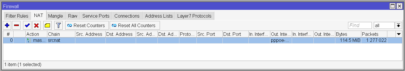
This might be one of the simplest steps along the way. Open up the IP -> Firewall window, go to the NAT tab and click on the Plus button. On the General tab select the srcnat chain and set pppoe-out1 as the interface. Now switch to the Action tab and select masquerade as the action and click OK.
Now you should have a working internet connection. Go check it out, browse your favorite site, or leave a comment on this post. But please don’t stop here. Currently, both your router and your network are vulnerable since we have no firewall configured.
Configure the firewall
Without a proper firewall, anyone can access your router from anywhere. We’re going to fix this.
You should still be on the IP -> Firewall window from the previous step. Let’s switch back to the Filter Rules tab. The list is going to be empty, which means that every traffic is allowed. Since NAT is enabled, an outside attacker would not be able to access the devices on your internal network, but they could access your router, which is equally dangerous, especially if you haven’t set up a secure password.
So let’s configure a firewall that will guard both your router and your devices. You can add the rules from the GUI, but for firewall rules, it’s actually much simpler to use the terminal interface of RouterOS. Believe me, it’s going to be much simpler than switching over that many tabs in the GUI. We’re still using the GUI to view the results of our commands, so don’t close that window, but click on the New Terminal button from the sidebar.
First of all, we will create an IP address list containing addresses that are not public and that we should not forward to/from. Let’s call this list bogus. It’ll contain the following CIDR blocks:
- 0.0.0.0/8
- 172.16.0.0/12
- 192.168.0.0/16
- 10.0.0.0/8
- 169.254.0.0/16
- 127.0.0.0/8
- 224.0.0.0/4
- 198.18.0.0/15
- 192.0.0.0/24
- 192.0.2.0/24
- 198.51.100.0/24
- 203.0.113.0/24
- 100.64.0.0/10
- 240.0.0.0/4
- 192.88.99.0/24
To do this using the terminal, we’re going to execute the following commands:
/ip firewall address-list
add address=0.0.0.0/8 list=bogus
add address=172.16.0.0/12 list=bogus
add address=192.168.0.0/16 list=bogus
add address=10.0.0.0/8 list=bogus
add address=169.254.0.0/16 list=bogus
add address=127.0.0.0/8 list=bogus
add address=224.0.0.0/4 list=bogus
add address=198.18.0.0/15 list=bogus
add address=192.0.0.0/24 list=bogus
add address=192.0.2.0/24 list=bogus
add address=198.51.100.0/24 list=bogus
add address=203.0.113.0/24 list=bogus
add address=100.64.0.0/10 list=bogus
add address=240.0.0.0/4 list=bogus
add address=192.88.99.0/24 list=bogus
The actual command each time would be ip firewall address-list add address=0.0.0.0/8 list=bogus but RouterOS scripting allows us to specify the first part of the command only once (the /ip firewall address-list line) and only use the subcommands from there on. The commands are represented like a directory structure in this system. It takes some time to get used to it, but I can promise you, that you’re going to love it. By the way: you can press F1 anytime in the terminal to get help in the context of the currently selected command or press Tab for auto-complete hints.
Now that we have our list of bogus addresses, we can configure our firewall rules. There will be two firewall chains we’re going to work with: input and forward. The input chain defines the rules that are checked when we’re accessing the router itself and the forward chain is used when the router does its job and forwards (routes) the packets.
Let’s start with the input chain. The ordering of the rules is important since they are checked from top to bottom. If a rule matches a network packet, the corresponding action is taken. If no rules match a packet, the default action is to allow it.
Our rules will do the following:
- [Accept] all the connections that are already established or are related to an established connection
- [Accept] anything using the ICMP protocol (like ping)
- [Accept] anything coming from our LAN network
- [Drop] everything else
The script to create these rules is the following:
/ip firewall filter
add chain=input action=accept connection-state=established,related comment="accept established and related"
add chain=input action=accept protocol=icmp comment="accept ICMP"
add chain=input action=accept in-interface-list=lan comment="accept from LAN"
add chain=input action=drop comment="drop everything else"
Have you noticed? We’re finally using the interface lists we’ve configured at the beginning!
Now we can continue with our forward chain, which will apply the following rules:
- [Fasttrack] the established and related connections using hardware offloading (it speeds up things)
- [Accept] the established and related connections
- [Drop] invalid connections
- [Drop] connections that try to reach a local address on the WAN
- [Drop] packets coming from the WAN that are not NAT’d
- [Drop] connections coming from the WAN that are using local addresses
- [Drop] connections originating from our LAN network that do not have LAN ips
- [Accept] anything coming from our LAN network
- [Drop] everything else
The RouterOS script to create these rules is the following:
/ip firewall filter
add chain=forward action=fasttrack-connection connection-state=established,related hw-offload=yes comment="fasttrack established and related"
add chain=forward action=accept connection-state=established,related comment="accept established and related"
add chain=forward action=drop connection-state=invalid comment="drop invalid"
add chain=forward action=drop in-interface-list=lan out-interface-list=wan dst-address-list=bogus comment="drop tries to reach local address on internet"
add chain=forward action=drop in-interface-list=wan connection-state=new connection-nat-state=!dstnat comment="drop no NAT"
add chain=forward action=drop in-interface-list=wan src-address-list=bogus comment="drop local address from internet"
add chain=forward action=drop in-interface-list=lan src-address=!10.10.0.0/16 comment="drop from lan without lan IP"
add chain=forward action=accept in-interface-list=lan comment="accept from LAN"
add chain=forward action=drop comment="drop"
After running these commands your firewall rules screen should look like this:
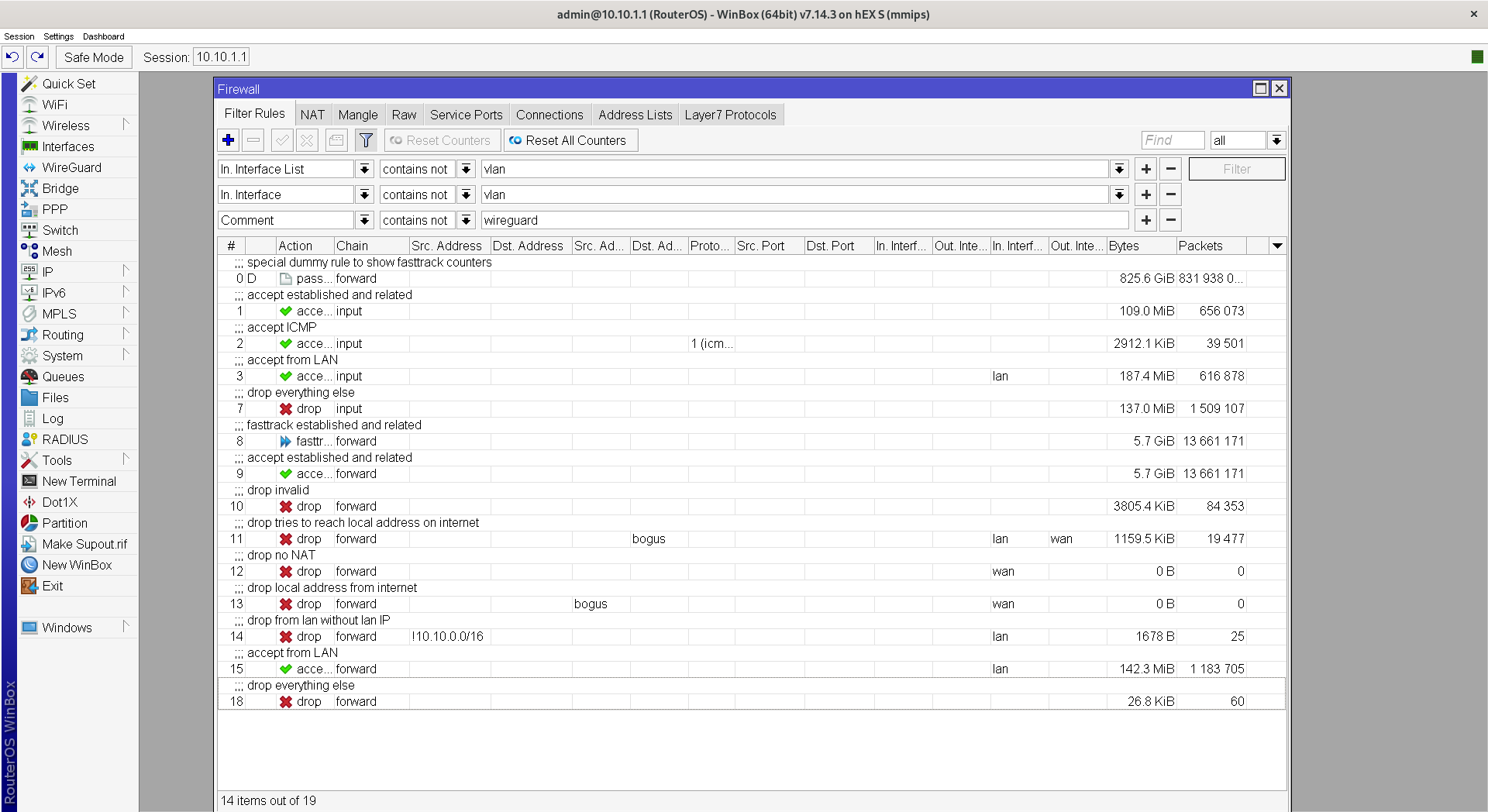
And now you’re all set. You should have a working internet connection and you should have a secure firewall. But there are some more changes I’d recommend to do.
Additional configurations
By default, a lot of settings are enabled on your router which are not required or configured in a way that is too permissive. We’re going to change these.
First of all, if you remember, at the beginning I said that WinBox can work through L2. But our firewall works on L3. This means that even though we restricted all access to our router to our LAN network, our ISP could still connect to our router through our WAN connection using it’s MAC address. This is unlikely to happen, but it’s best to avoid any security risks.
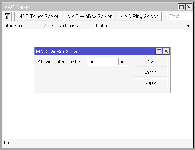
RouterOS allows us to restrict access to the MAC server to specific interfaces. To do this open the Tools -> MAC Server window from the sidebar and click on the MAC Telnet Server and MAC WinBox Server buttons and change the Allowed Interface List to lan.
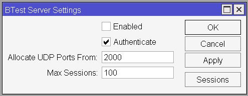
Now we should also disable the BTest Server. To do this open the Tools -> BTest Server window and uncheck the Enabled checkbox.
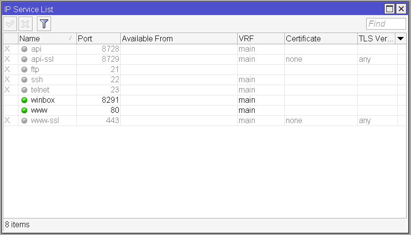
As I’ve said earlier, RouterOS can be accessed through a multitude of interfaces, including an API, FTP, SSH, Telnet, Web, and of course WinBox. We don’t need all of these interfaces, so let’s disable most of them. Open up the IP -> Services window and disable everything except winbox (this is for the WinBox connection made with an IP address, not the MAC address based version) and www (if you’d like to access your router’s web interface once in a while). You can disable the services by selecting them and clicking on the cross button.
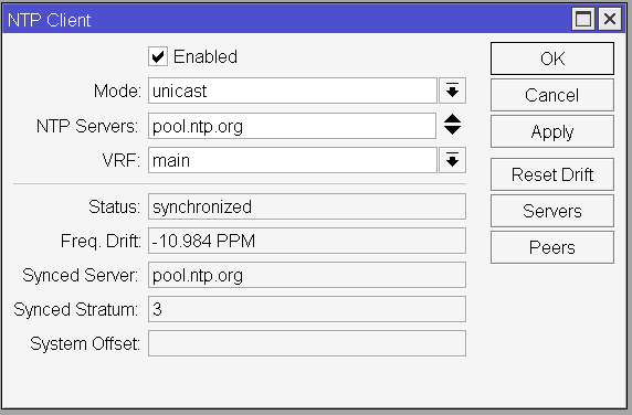
As a finishing touch, we’re going to configure the internal clock of the router to synchronize with NTP. To do this open up the System -> NTP Client window and check the enabled checkbox, select Unicast mode, and for the NTP server enter pool.ntp.org or your country’s/continent’s specific NTP pool which can be found on this site. It might take a minute or two, but then you will see that the Status field changes to synchronized.
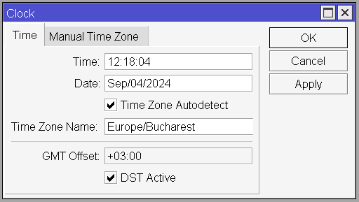
Your timezone should be automatically detected by default, but if it’s not alright, you can open the System -> Clock window and set it manually. This is the place from where you can also enable/disable DST manually if you desire to do so.
Closing thoughts
Now you should have your router up and running which should serve you well on a day-to-day basis. MikroTik’s routers are robust and reliable, this is why I recommend them to people. They can easily outperform a “high-performance gaming” router and offer features that are otherwise only available on enterprise routers (like BGP). My 80$ hEX S has an estimated MTBF of 100000 hours on 25°C and I’ve never needed to reboot for anything else than software updates.
Speaking of software updates, MikroTik offers free software updates for at least 5 years after the product’s end of life, which is a huge advantage compared to some of the more common brands which rarely publish any updates.
Now feel free to tinker with your router and explore its options and features. Don’t be afraid that you mess up something. There is a Safe Mode button on the header of WinBox. If you enable it and break something, every setting will be reset to its original state if you end your session (close WinBox). If you’re happy with your changes though, just press the button again and it will save them.
If you have any questions, feel free to comment below, reach out to us at [email protected], or turn to our network management services.
Coming up…
In part 2 I’ll be showing you how to set up IPv6, VLANs, and a VPN using WireGuard.
Comments